 English
 русский
 Français
 Español
 عربى
عربى
A laminated core distribution transformer is a classic power device applied to voltage conversion and power transmission. This transformer enjoys mature technical performance, high operation reliabili...
See Details

Content
A 10 kV feeder supplied a 1600 kVA distribution transformer. A bolted external fault occurred on the cable box, and the feeder protective relay did not issue a trip command for almost five seconds. The transformer tank, although undamaged externally, was later found to have severe winding displacement. The relay technician who investigated the disturbance record saw a second harmonic content that appeared almost immediately after the fault started. The current transformer at the star point had saturated in the first cycle.
That event is not unusual. CT saturation remains one of the most common reasons protection systems behave unpredictably. The key conclusion is that saturation is not a relay setting problem that can be solved entirely in software. It is influenced by the CT specification, the connected burden, and the physical condition of the magnetic core. If you are involved in specifying transformers or switchgear, it is worth understanding how saturation begins and what you can do to prevent it.
An ideal CT would reproduce the primary current on the secondary side with exact proportionality at every instant. In practice, the magnetic core has a finite flux capacity. When the flux density reaches the knee point, the magnetising current rises rapidly and the core cannot deliver the required secondary voltage. The secondary current is no longer a scaled image of the primary current.
The condition occurs whenever the required secondary voltage exceeds the knee point voltage. This usually happens when the primary current is many times higher than the rated value, especially during asymmetric faults. The DC component of an asymmetrical fault shifts the flux in the core so that saturation starts earlier and is deeper. A CT that performs well at rated load may saturate in less than half a cycle under high fault current.
| Parameter | Normal linear operation | Saturated operation |
|---|---|---|
| Core flux | Below knee point | Above knee point |
| Secondary current | Proportional to primary | Distorted and flattened |
| Relay response | Correct waveform | Reduced or false current |
| Protection action | Reliable trip | Delayed or unwanted trip |
In protection terms, the important figure is the accuracy limit factor. A class 5P20 CT guarantees a compound error below 5% at twenty times the rated primary current, provided the burden does not exceed the rated burden. If the maximum fault current at the installation is forty times rated current, the CT is likely to saturate even though it is marked 5P20.
The immediate effect is that the protection relay receives a distorted version of the fault current. A saturated CT produces a secondary current with a recognisable flattened peak and a significant harmonic content. The result is one of the following:
The practical consequence is not limited to the protection scheme. A delayed trip increases the energy let-through to transformers, cables, and busbars. In the case of a transformer, winding displacement can occur before the fault is isolated. The repair or replacement cost is then much higher than the cost of selecting protection-grade CTs correctly.
Saturation can also cause unwanted nuisance trips. On a lightly loaded feeder, a CT saturation event caused by inrush current may be misinterpreted as a fault. Modern relays use harmonic blocking or waveform identification, but the physical CT still has to have enough copper and core area to handle the inrush without losing proportionality.
There is no shortcut around the saturation calculation. The protective relay can use algorithms that detect saturation and temporarily block the differential element, but that is a mitigation technique, not a substitute for proper CT sizing. A relay can detect saturation after it occurs; it cannot prevent the core from saturating.
The engineering approach is to specify the CT by the worst-case fault current and the external burden:
It is also important to check the residual flux in the core before a fault. Re-magnetisation can lower the usable flux range and cause earlier saturation. Some relay schemes deliberately insert a small time delay to avoid tripping on transient saturation, but the delay only works if the CT returns to the linear region quickly.
The simplest field check is to apply a variable power-frequency voltage to the secondary winding and plot the magnetising current. The knee point appears when the current starts to rise sharply. If the measured knee point voltage is below the value calculated for the fault current, the CT will saturate under that fault. This test should be part of commissioning, not something left to a later troubleshooting session.
When a transformer is purchased for a project, attention naturally goes to efficiency, dimensions, and price. The associated CTs are often in the switchboard specification and can be treated as an afterthought. Yet transformer protection is only as dependable as the CTs that feed the relay. In our work with distribution transformers, we have consistently seen that a site with correct CT saturation studies has a much lower risk of unexpected trips. For example, the amorphous alloy distribution transformer we manufacture has extremely low no-load losses, but it still needs a protection CT with enough saturation margin for a terminal fault.
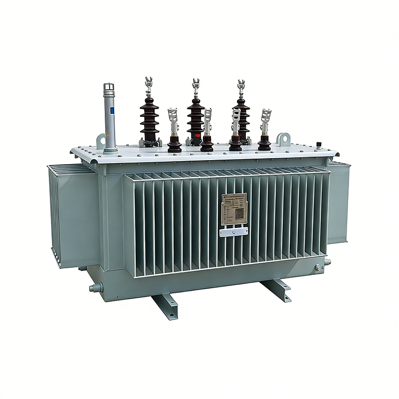 Amorphous Alloy Non-distribution Transformer for Industrial Power DistributionThis transformer offers extremely low no-load losses and a fully sealed oil-immersed design. Its protection relies on correctly sized CTs with sufficient saturation margin to avoid unexpected trips during terminal faults.View Product →
Dry-type transformers are a separate case. Their location inside or near a building often calls for more sensitive protection to minimise fire risk. The fire-sensitive environment means the trip time should be short, but a quickly saturated CT can prevent the relay from seeing the true current level. Our dry-type distribution transformer range is designed with conservative thermal margins so that under overload conditions the protection has time to operate, while the CT can still reproduce a faithful current during the first cycles of a fault.
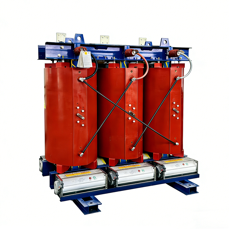 Dry-type Distribution Transformer with Epoxy Resin Cast InsulationDesigned for fire-sensitive indoor environments, this transformer features flame-retardant, maintenance-free construction. Its protection requires short trip times, but conservative thermal margins allow CTs to reproduce fault current reliably.View Product →
Marine installations introduce an additional layer of complexity because fault currents are often high and the supply network is isolated. A water-cooled marine transformer in a ship's engine room may be supplied from a generator whose X/R ratio is high, producing a strong DC offset that can saturate CTs even during moderate faults. We have delivered marine transformers where the project engineer explicitly required a CT saturation check for the star-point current transformer. The transformer is built for a salt-laden environment; the protection design still depends on the same CT sizing rules.
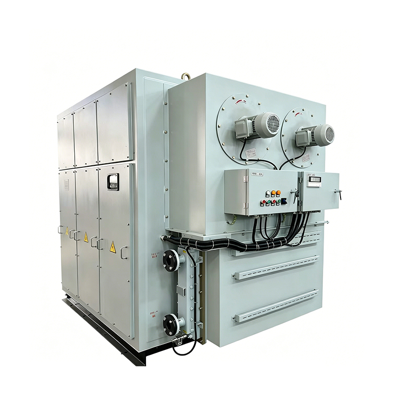 Marine Water-cooled Transformer for Ships and Offshore PlatformsBuilt for harsh marine conditions with salt-spray, mold, and humidity resistance. In isolated ship networks with high X/R ratios, proper CT saturation checks are essential for dependable protection.View Product →
At the switchboard level, the CTs are mounted inside the medium-voltage switchgear, and their performance cannot be separated from the rating of the feeder. A KYN28 switchgear, for instance, can have widely different CT saturation behaviour depending on the core material and secondary winding. The switchgear supplier should provide the CT class and knee point voltage, not just the current ratio.
If you need a more practical example of CT sizing on marine equipment, our article on marine transformer design standards and selection tips covers the key parameters. For broader system questions, the solutions section of our site explains how transformer and switchgear selection fits with protection coordination.
The lesson is straightforward. CT saturation is a specification issue that crosses the boundary between transformers, switchgear, and relay settings. A few extra minutes spent on saturation analysis at the design stage can prevent a protection misoperation that leads to months of downtime. If you are replacing equipment or building a new substation, ask the switchgear supplier to provide the CT knee point voltage for the worst-case fault, and do not accept a generic 5P20 class without a calculation.
Ultimately, reliable protection depends on the whole chain: the transformer, the switchgear, the CTs, and the relay. A transformer manufacturer can offer an efficient and robust unit, but the protection performance still rests on the CTs that are installed around it. Make sure that the CT saturation check is part of your next procurement conversation.
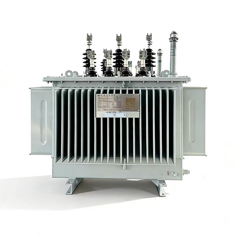
A laminated core distribution transformer is a classic power device applied to voltage conversion and power transmission. This transformer enjoys mature technical performance, high operation reliabili...
See Details
The amorphous alloy non-distribution transformer adopts an iron-based amorphous alloy wound core and a fully sealed oil-immersed corrugated oil tank structure. This transformer features extremely low ...
See Details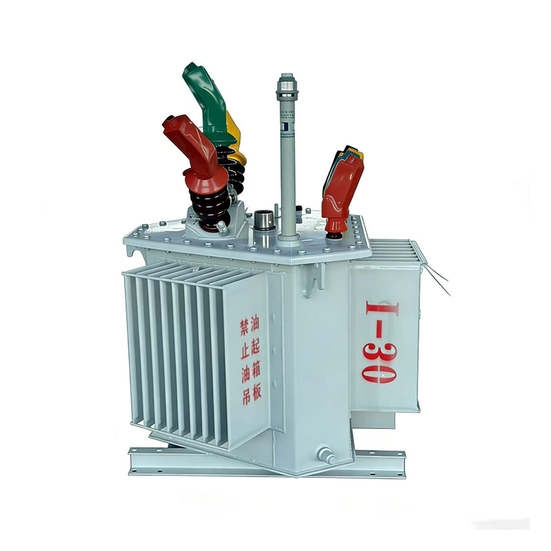
Three-dimensional Wound Core Distribution Transformer. The oil-immersed three-dimensional wound core distribution transformer adopts high-quality cold-rolled oriented silicon steel sheets formed throu...
See Details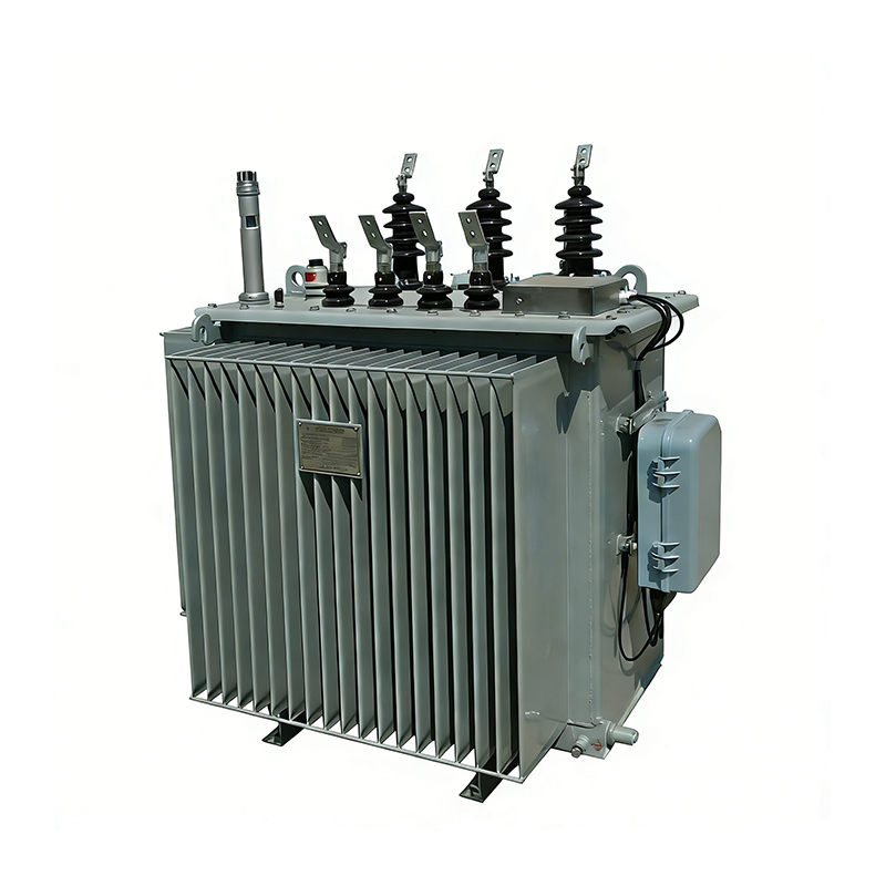
The oil-immersed on-load tap-changing distribution transformer adopts a high-quality laminated silicon steel core and oxygen-free copper windings with a stable structure and strong short-circuit resis...
See DetailsHey! Interested in staying in the loop? Sign up for our updates. We won't spam you, pinky promise.

Taizhou Haitian Electric Manufacture Co., Ltd.
