 English
 русский
 Français
 Español
 عربى
A laminated core distribution transformer is a classic power device applied to voltage conversion and power transmission. This transformer enjoys mature technical performance, high operation reliabili...
See Details

Content
Every protection and metering scheme starts with a number on a nameplate. A 1000/5 current transformer promises a twenty-to-one transformation, and the whole relay coordination study is built on that promise. A current transformer ratio test is simply the moment of truth: it applies a known current or voltage to one winding, measures what comes out of the other, and compares the result with the nameplate. Done well, it confirms that the CT, its wiring and its secondary circuits are healthy. Done carelessly, a wrong ratio can sit quietly in the system until the day a fault current arrives and the relay either fails to operate or trips when it should not.
At its core, a current transformer behaves like any other transformer: the number of turns between the primary and the secondary sets the relationship between the two windings. Because the primary is effectively a single turn, or a small number of turns, carrying the full line current, the secondary delivers a scaled-down copy, conventionally 5 A or 1 A at rated primary current. The ratio test verifies two things at once. First, that the turns ratio is what the nameplate claims. Second, that the magnetic circuit still behaves well enough at the test current to produce a clean, measurable output.
Engineers usually run this test for one of three reasons. During commissioning of a new substation, every CT must be proven before protection is enabled. During routine maintenance, a drift in the measured ratio hints at shorted turns, loose terminal connections or moisture in the insulation. And during troubleshooting, when a relay has misoperated or a meter has recorded energy that does not add up.
Whatever the reason, the test needs a reference point. The rated ratio is the nameplate figure, for example 400/5 or 1000/5. The measured ratio is what you actually inject and observe. The difference between them, expressed as a percentage, is the ratio error that decides whether the CT is still fit for its accuracy class.
In practice there are two main approaches, plus a third that automates both.
A high-current source injects a known current into the primary winding while the output is read on the secondary. The ratio is simply the injected primary current divided by the measured secondary current. This is the most convincing test when you want to prove the entire loop, because the wiring, terminals and shorting links are all inside the measurement circuit. Watch out for saturation: if you inject far below rated current, the measured ratio may drift slightly, so keep the injection within a sensible band of the CT rating or accept a modest extrapolation.
A low alternating voltage is applied to the primary winding and the induced voltage is measured on the secondary. The voltage ratio follows the turns ratio, so no heavy current is needed to obtain a fast and clean ratio figure. It is an excellent bench check and a convenient field method when the primary circuit cannot be opened or a high-current set is not available. The secondary must never be left open, however, because dangerous voltages can appear across the terminals.
| Method | What you apply | What you measure | Best suited for | Key caution |
|---|---|---|---|---|
| Primary current injection | Known current on the primary | Secondary current | Proving the complete loop including wiring | Heavy, hot conductors; keep below saturation |
| Secondary voltage method | Low AC voltage on the primary | Induced secondary voltage | Quick turns ratio checks in the workshop | Never leave the secondary open |
| Automatic CT analyzer | Programmed current or voltage sweep | Ratio, polarity, excitation, burden | Commissioning reports and repeat tests | Test leads and grounding still decide accuracy |
Modern automatic CT analyzers combine these checks in a single pass and calculate ratio, polarity, excitation knee point and secondary burden according to IEC 61869-2 or IEEE C57.13, which saves considerable time on a busy commissioning schedule.
When a ratio reading disagrees with the nameplate, there are several common culprits worth ruling out before condemning the CT.
The arithmetic is straightforward: ratio error in percent equals the measured ratio minus the rated ratio, divided by the rated ratio, multiplied by one hundred. For metering cores, a deviation within roughly plus or minus 0.5 percent is normally acceptable, while a class 0.2 unit demands tighter control. Protection cores tolerate a wider ratio deviation, but they must still pass their excitation characteristic. A practical field rule is that anything beyond 1 percent deserves investigation, and anything beyond 5 percent usually points to shorted turns, miswiring, or a tap that does not match the drawing.
Ratio is only one item on the list. Polarity, excitation or saturation curve, insulation resistance, winding resistance and secondary burden together form the complete CT commissioning set, which is why a modern test set runs them in sequence. Polarity deserves a special mention: if S1 and S2 are reversed, a differential relay will see a current that does not exist and may operate without any fault present.
A ratio test rarely happens in isolation. It takes place inside a switchgear cubicle, at a box-type substation, or beside a distribution transformer, where the secondary circuits are shared and the burden is the sum of every connected load. That reality shapes the way complete equipment should be assembled and tested. An oil-immersed on-load tap-changing distribution transformer, for example, carries its own bushing current transformers and its own protection arrangement, and the methods used to verify those CTs are identical to the ones used for standalone units in a cubicle.
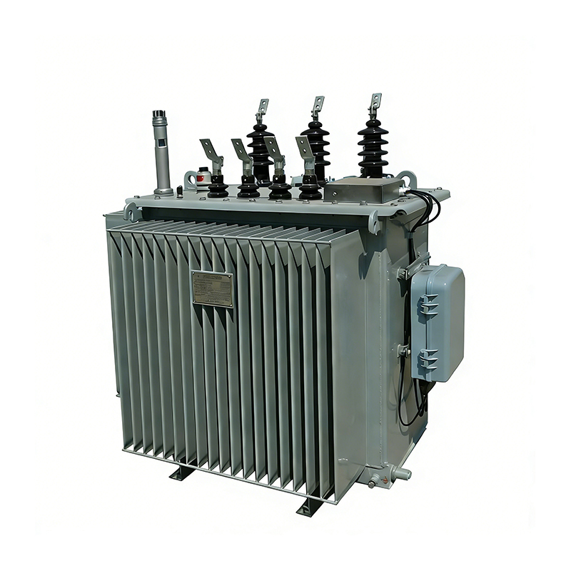 Oil-immersed On-load Tap-changing Distribution TransformerThe oil-immersed on-load tap-changing distribution transformer adopts a high-quality laminated silicon steel core and oxygen-free copper windings with a stable structu...View Product →
If the CT lives on oil-immersed equipment, it makes sense to fold the electrical test into a wider overhaul plan: oil analysis, gasket inspection, trend records and protection re-verification all belong to the same outage window, exactly as described in these oil-immersed transformer maintenance notes.
The same logic applies to air-insulated equipment. A dry-type distribution transformer feeding a commercial or industrial load is usually protected by CTs whose ratio, class and burden were chosen to match the downstream relay, so verifying the ratio at commissioning protects the investment in the whole assembly.
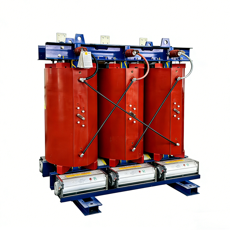 Dry-type Distribution TransformerThe dry-type distribution transformer adopts an epoxy resin cast insulation structure, which is non-toxic, flame-retardant, safe, and environment-friendly with high me...View Product →
At the point where the CT actually sits, the medium-voltage switchgear decides how accessible it will be for future testing. Cubicles designed with adequate CT compartments and clearly labeled secondary terminals make routine verification a short, safe job rather than a full-day shutdown.
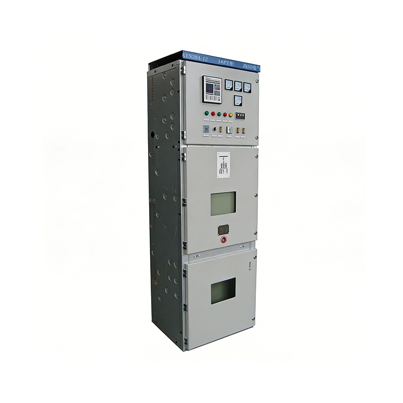 KYN28 Medium-mounted High-voltage SwitchgearThe KYN28 medium-mounted high voltage switchgear adopts a metal armored, removable enclosed structure. The switchgear has clear internal compartments and reliable safe...View Product →
A current transformer ratio test takes less time than almost any other task on a commissioning schedule, yet it sits underneath every decision the protection system will later make. Confirming the ratio, the polarity and the burden means the relay sees current the way the design intended. Skipping it leaves a compromise that stays invisible until the one day it matters most.
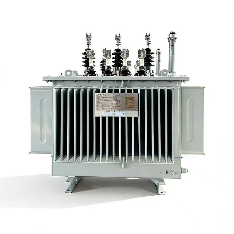
A laminated core distribution transformer is a classic power device applied to voltage conversion and power transmission. This transformer enjoys mature technical performance, high operation reliabili...
See Details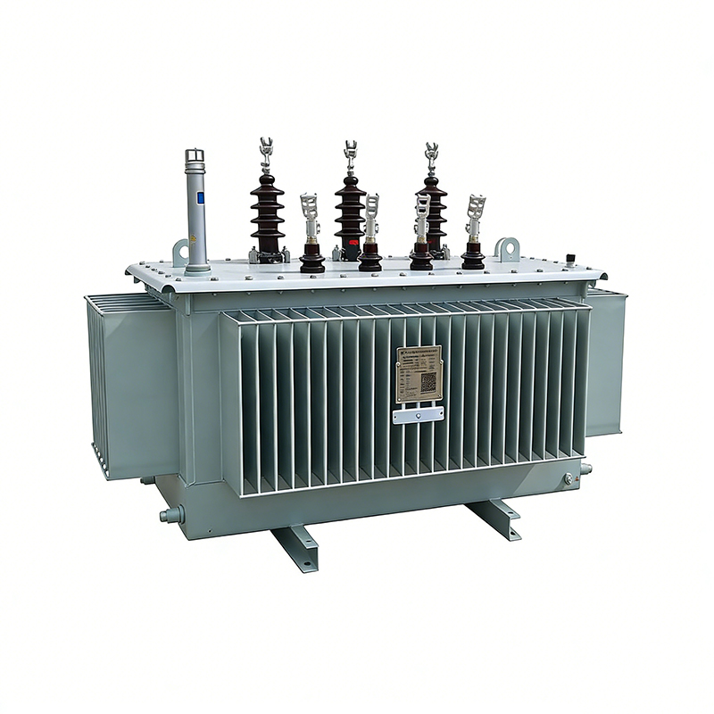
The amorphous alloy non-distribution transformer adopts an iron-based amorphous alloy wound core and a fully sealed oil-immersed corrugated oil tank structure. This transformer features extremely low ...
See Details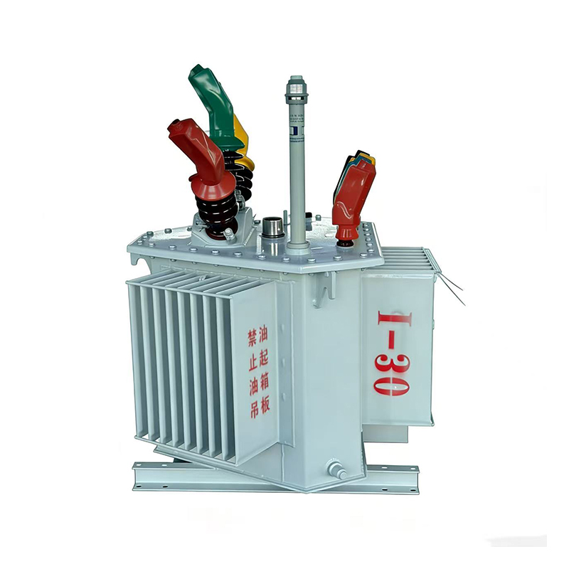
Three-dimensional Wound Core Distribution Transformer. The oil-immersed three-dimensional wound core distribution transformer adopts high-quality cold-rolled oriented silicon steel sheets formed throu...
See Details
The oil-immersed on-load tap-changing distribution transformer adopts a high-quality laminated silicon steel core and oxygen-free copper windings with a stable structure and strong short-circuit resis...
See DetailsHey! Interested in staying in the loop? Sign up for our updates. We won't spam you, pinky promise.

Taizhou Haitian Electric Manufacture Co., Ltd.
