 English
 русский
 Français
 Español
 عربى
عربى
The amorphous alloy non-distribution transformer adopts an iron-based amorphous alloy wound core and a fully sealed oil-immersed corrugated oil tank structure. This transformer features extremely low ...
See Details

Content
A procurement engineer opens three bids for a 1000 kVA distribution transformer. All three technical sheets show "1000 kVA, 11/0.4 kV, Dyn11," yet one bid is rejected after checking the nameplate data: the impedance is 4 percent instead of the 6 percent used in the substation short-circuit study. The nameplate of a 1000 kVA transformer is not a decorative plate. It is the contractual statement of how the unit behaves in service, which protections it needs, and what thermal limits it can tolerate. This guide explains every relevant field on a 1000 kVA transformer nameplate and how to use that data when ordering a replacement or a new unit.
A 1000 kVA transformer nameplate consolidates the electrical, mechanical, and thermal limits that the manufacturer guarantees under specified operating conditions. Standards such as IEC 60076 and GB 1094 define the minimum content.
A typical plate for a three-phase 1000 kVA distribution unit carries the following information:
One point is frequently overlooked: nameplate ratings are valid at the reference ambient conditions stated in the standard. If the installation site runs hotter or sits above 1,000 m altitude, the permissible continuous loading is lower than the nameplate value.
The 1000 kVA figure is the continuous apparent power the unit can deliver at rated voltage and frequency without exceeding the temperature-rise limit. Real power in kW depends on the load power factor, so a 1000 kVA transformer can supply 800 kW at 0.8 power factor or 950 kW at 0.95 power factor, as long as the current stays within the rated value.
Full-load currents are derived from the kVA and voltage combination, and they determine relay settings, busbar and cable sizing, and the upstream breaker rating.
| HV Voltage | LV Voltage | HV Full-Load Current | LV Full-Load Current |
|---|---|---|---|
| 11,000 V | 415 V | 52.5 A | 1,391 A |
| 10,000 V | 400 V | 57.7 A | 1,443 A |
| 6,600 V | 415 V | 87.5 A | 1,391 A |
| 3,300 V | 415 V | 175 A | 1,391 A |
Note that the kVA rating does not tell you the losses; those appear on the test report or on an efficiency label.
The voltage notation shows the rated line-to-line voltages of the HV and LV windings. A unit marked 11,000 / 400 V has an 11 kV primary and a 400 V secondary. Check whether the nameplate states no-load voltage or voltage at rated load; at full load the secondary voltage drops by an amount that depends on impedance and load power factor.
Rated currents on the nameplate follow from the three-phase relationship I = S / (√3 × V). For a 1000 kVA unit at 11 kV the HV current is 52.5 A, while the LV current at 415 V reaches 1,391 A. That contrast explains why LV connections need much larger conductors.
A 1000 kVA distribution transformer is normally three-phase. The nameplate states the phase count and the rated frequency. A 60 Hz unit can operate on 50 Hz only with a proportional reduction in voltage and kVA; otherwise the core saturates. If the frequency does not match the network, reject the unit.
The vector group, such as Dyn11, defines the winding connection and the phase displacement between HV and LV sides. For parallel operation, transformers must have the same phase displacement, matched voltage ratios, and compatible impedance. Paralleling a Dyn11 unit with a Dyn1 unit without cross-connecting phases is a costly mistake.
Impedance voltage, %Z or uk%, is the primary voltage required at rated frequency to circulate rated current with the secondary short-circuited, expressed as a percentage. A 1000 kVA oil-immersed distribution transformer commonly has an impedance between 4.5 and 6 percent.
The %Z value has direct consequences:
When evaluating bids, ask for a short-circuit calculation based on the offered %Z, not just the kVA rating.
The cooling class defines the cooling medium and circulation method. Oil-immersed units are typically ONAN (Oil Natural, Air Natural); forced-air versions are rated ONAF. Dry-type transformers use AN (Air Natural) or AF (Air Forced).
The temperature rise is the maximum permitted winding temperature increase above reference ambient. Oil-immersed transformers are typically rated for 65 K average winding rise above a 40 °C maximum ambient; dry-type units are rated for 75 K or 100 K depending on insulation class.
If the site ambient temperature exceeds the reference value, derating is required. A 1000 kVA ONAN unit in a poorly ventilated indoor vault may carry only 800 to 900 kVA in summer. Thermal overload relays are set using the temperature-rise field on the nameplate.
Most 1000 kVA distribution transformers have an off-circuit tap changer on the HV winding. The nameplate tap table lists HV voltages, typically the rated voltage plus and minus 2×2.5 percent, or in simpler versions ±5 percent in one or two steps. Taps are adjusted only when the transformer is de-energized.
For a site with consistently low supply voltage, selecting the correct tap restores the LV voltage. A +5 percent tap on a nominal 11 kV winding corresponds to 11,550 V and raises the LV voltage at the same primary voltage.
When voltage must be regulated under fluctuating load without interrupting supply, an on-load tap-changing distribution transformer is used. Its nameplate includes a wider range such as ±8×1.25 percent and designates the motor-drive mechanism.
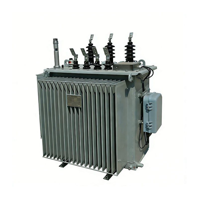 Oil-immersed On-load Tap-changing Distribution TransformerThis transformer regulates voltage under load without interrupting supply, using an on-load tap changer. Its nameplate lists total and transport weight and oil volume, which are essential for logistics and bunded-area design.View Product →
The lower part of the nameplate carries mechanical data that is easy to ignore but essential for logistics. Total weight sets the crane capacity; transport weight may be lower for units shipped without oil. Oil volume is needed for bunded-area design, top-up quantities, and disposal planning.
The serial number and year of manufacture link the unit to its routine test report and identify spare parts such as tap switches, bushings, and gaskets. On an older unit with a lost report, the nameplate is often the only reliable source for re-commissioning data.
Maintenance planning also starts from the nameplate. Oil test intervals and dielectric limits are based on rated data; the relationship between loading, aging, and service life is covered in the oil-immersed transformer maintenance and lifespan guide.
When ordering a new 1000 kVA transformer, use the existing unit's nameplate data as the baseline specification: voltage combination, vector group, tap range, impedance, cooling class, and footprint. Then compare each bidder's proposed nameplate against that baseline.
For an indoor or fire-sensitive installation, a dry-type distribution transformer removes the oil containment requirement. For an outdoor substation, an oil-immersed laminated-core distribution transformer is the conventional economical choice. Either type must show compliance with the applicable standard and declared losses.
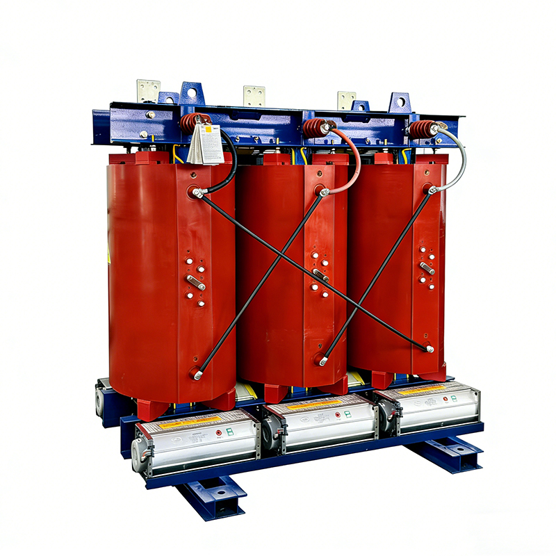 Dry-type Distribution TransformerSuitable for indoor or fire-sensitive installations, this cast-resin transformer is flame-retardant and maintenance-free. Verify its routine test report so measured losses and impedance match nameplate values within tolerance.View Product →
 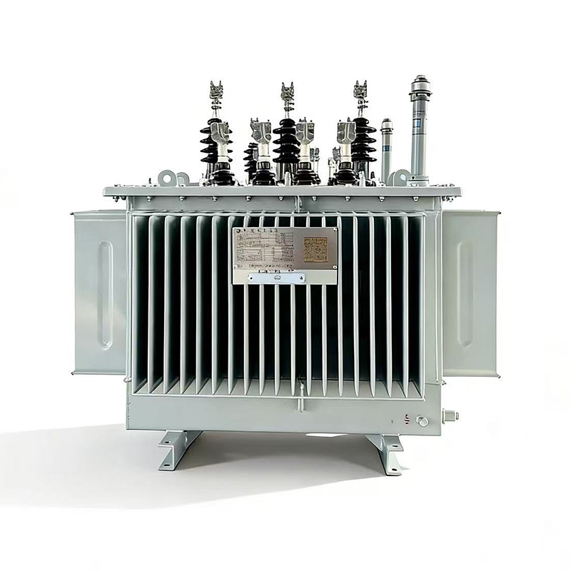 Laminated Core Distribution TransformerA conventional economical oil-immersed choice for outdoor substations, this laminated-core unit offers mature performance. Confirm its nameplate complies with the applicable standard and that declared losses meet project efficiency verification.View Product →
Before placing the order, request the routine test report and verify that measured losses and impedance match the nameplate values within permitted tolerances. A 1000 kVA unit with higher than declared losses can fail the project's efficiency verification. You can also browse the full transformer product range to compare how core material and casing type affect the nameplate ratings.
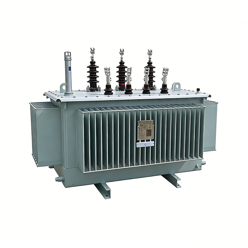
The amorphous alloy non-distribution transformer adopts an iron-based amorphous alloy wound core and a fully sealed oil-immersed corrugated oil tank structure. This transformer features extremely low ...
See Details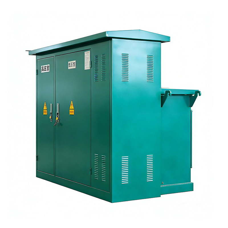
The American-type box substation is a compact prefabricated substation that integrates a transformer, high and low voltage switches, fuses, metering devices, and other components. The American-type bo...
See Details
A laminated core distribution transformer is a classic power device applied to voltage conversion and power transmission. This transformer enjoys mature technical performance, high operation reliabili...
See Details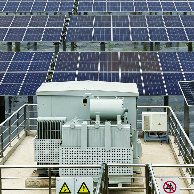
The photovoltaic prefabricated substation is mainly applied to photovoltaic power generation systems. The photovoltaic prefabricated substation steps up low-voltage electric energy gathered by photovo...
See DetailsHey! Interested in staying in the loop? Sign up for our updates. We won't spam you, pinky promise.

Taizhou Haitian Electric Manufacture Co., Ltd.
