 English
 русский
 Français
 Español
 عربى
The American-type box substation is a compact prefabricated substation that integrates a transformer, high and low voltage switches, fuses, metering devices, and other components. The American-type bo...
See Details

Content
Most people never see switchgear. It sits behind a locked door at the end of a corridor, or in a steel enclosure beside a transformer yard, humming quietly at fifty or sixty hertz. And yet almost every building, plant, ship and solar farm depends on it. If you have ever asked yourself how does switchgear work, the short answer is that it does three things at once: it carries current all day without complaint, it watches for trouble, and it cuts the power fast when trouble arrives.
Our own story in Taizhou goes back to 1958, when the factory that became this company started winding transformers. Over the decades we have built transformers, box substations and low and medium voltage switchgear for utilities, industry and marine projects, and the questions we get from customers are almost always the same ones. So here is a plain-language walkthrough, without the marketing fog.
Switchgear is a coordinated assembly, not a single device. Inside one enclosure you will usually find circuit breakers, disconnect switches, busbars, current transformers, protective relays, fuses, metering and a control panel, all mechanically and electrically designed to work together. That assembly performs three jobs:
The enclosure matters as much as the devices inside it. Compartmentalisation, interlocking, earthing switches and arc-rated construction are what turn a collection of components into equipment you can operate and maintain without putting anyone at risk.
The working principle is a loop rather than a single action. In a typical medium voltage feeder it runs in roughly this order:
A short circuit can reach tens of thousands of amps in a few milliseconds. The whole detection-and-trip chain usually needs to complete in well under a tenth of a second, because the energy released is proportional to both the current and how long it flows. Protection settings are therefore coordinated between upstream and downstream devices so that only the nearest breaker trips, and the rest of the network keeps running.
Before anyone opens a panel, the circuit is isolated, the withdrawable breaker may be racked out to a test or disconnected position, an earthing switch is closed onto the cable side, and the condition is confirmed by a voltage presence indicator or live-line test. That sequence is what makes maintenance possible on a network that cannot simply be switched off everywhere.
Different manufacturers arrange the interior differently, but the essential components are consistent:
On the low voltage side, the arrangement is more compact and often air-insulated, with air circuit breakers or moulded case devices doing the interrupting. Panels of this type handle final distribution in plant rooms and commercial buildings, and the layout is designed so a single faulty outgoing circuit can be changed without disturbing its neighbours.
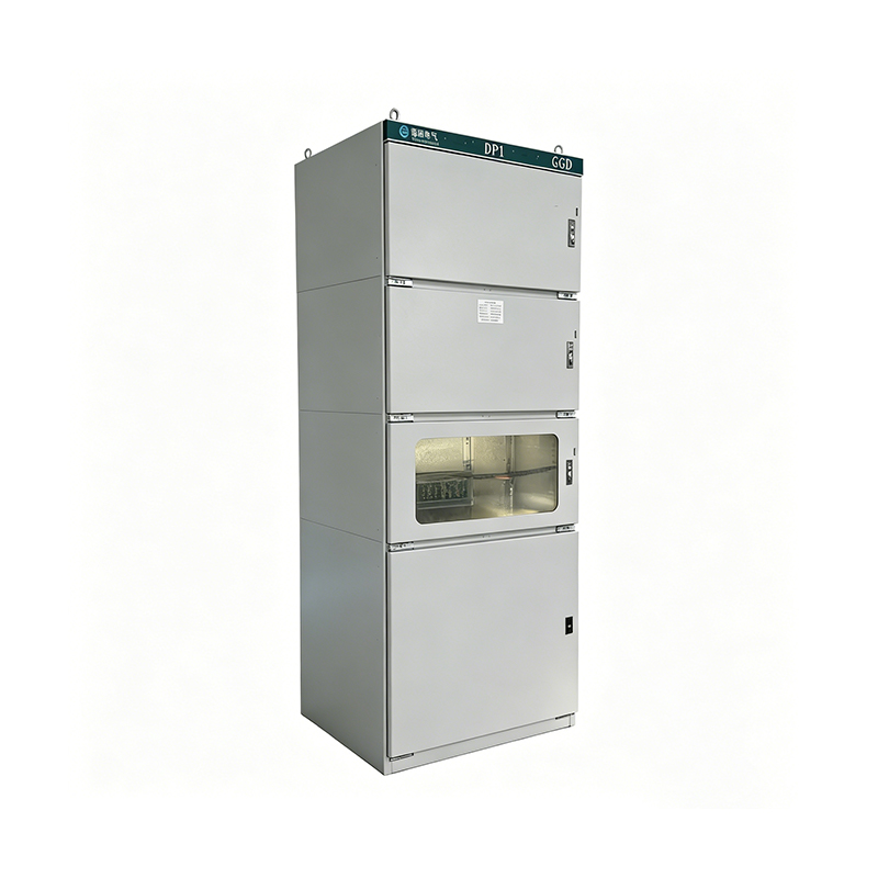 GGD Low Voltage Switchgear for Distribution and Power ControlLow-voltage distribution and power control switchgear with high breaking capacity and complete internal circuit configuration, suited to plant rooms, commercial buildings and municipal projects.View Product →
At medium voltage the equipment becomes taller, more heavily compartmentalised, and usually withdrawable, so a breaker can be removed for service while the busbar stays live.
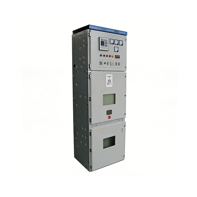 KYN28 Medium-Voltage Metal-Armored Withdrawable SwitchgearMetal-armored withdrawable switchgear with handcart breakers, five-prevention interlocks and integrated protection, measurement and control for substations and industrial distribution.View Product →
The principle stays the same across the range; the hardware, clearances and testing do not. The table below is the quick version we usually sketch on a whiteboard during a technical discussion.
| Voltage class | Typical range | Usual interrupting medium | Where you meet it |
|---|---|---|---|
| Low voltage | Up to 1 kV | Air, with air or moulded case breakers | Plant rooms, commercial distribution, GGD style panels |
| Medium voltage | 1 kV to 36 kV | Vacuum, occasionally gas | Incoming feeders, ring main units, KYN28 style panels |
| High voltage | Above 36 kV | Gas or vacuum | Bulk supply and transmission substations |
Every time a circuit breaks under load, or trips under fault, the current keeps flowing briefly through ionised air. That arc is hot, bright and destructive, and the entire mechanical design of a breaker is organised around getting rid of it quickly. Vacuum interrupters do it by letting the arc dissipate in a sealed bottle where contact material vapour condenses within milliseconds. Gas-insulated designs use a dense insulating gas to cool and extinguish the arc, which is why they can be built so compactly. Air breakers rely on lengthening and cooling the arc with a chute, and oil breakers, now largely historic at medium voltage, used the oil itself for both insulation and arc suppression.
That is also why switchgear is rated not just in amps but in short-circuit breaking capacity. A panel that carries 630 A happily may still need to interrupt 25 kA without coming apart.
Switchgear rarely works alone. On a typical distribution site, the incoming medium voltage feeder enters a switchgear panel, the transformer steps the voltage down, and a low voltage panel distributes it to loads. The protection settings on either side have to be coordinated, because a transformer is both a valuable asset and a source of inrush current that must not be mistaken for a fault. This is the pairing we spend most of our time on, and it is why our range covers transformers, box substations and switchgear together rather than as isolated items.
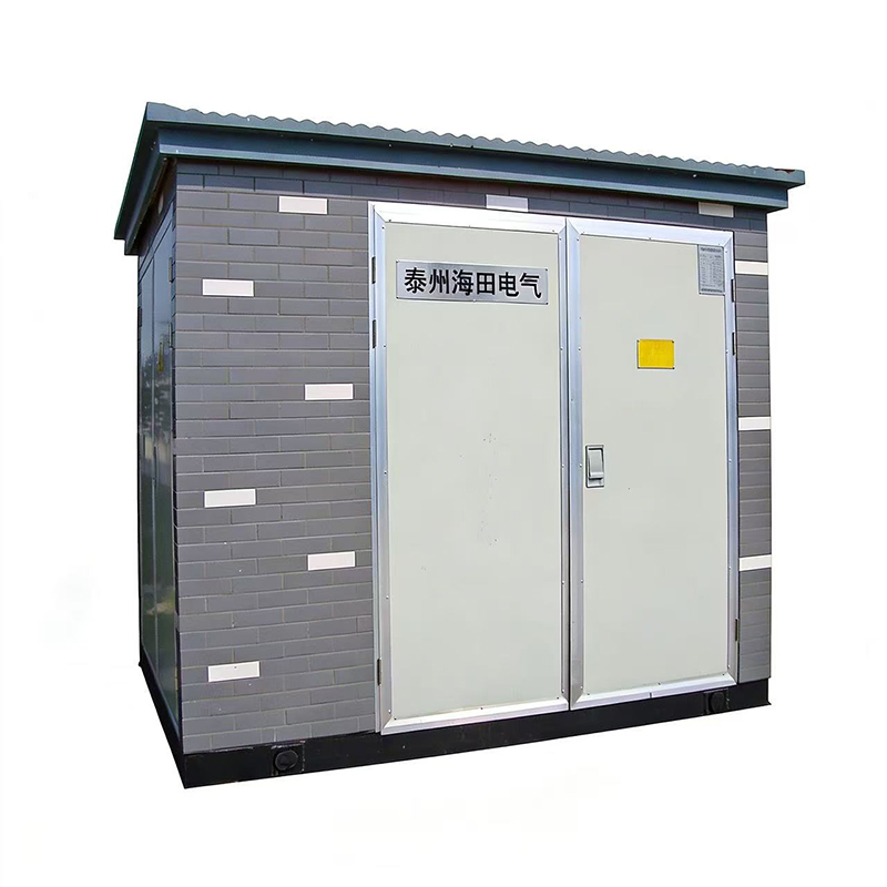 European-Type Box Substation for Integrated Outdoor DistributionA prefabricated substation combining high-voltage distribution, transformer, low-voltage distribution, protection and metering in a weather-resistant enclosure for outdoor projects.View Product →
The same logic travels to sea. Marine and offshore installations need compact, corrosion-resistant equipment, and water-cooled transformers alongside protective panels are common where ventilation is limited. On land, packaged substations simply bring the components into one weatherproof enclosure, so the switchgear, transformer and low voltage distribution arrive as a single tested unit. If you want a deeper look at the transformer half of that relationship, we have written about how an oil-immersed transformer works and how long it lasts.
When a customer sends us a single line diagram, these are the items we work through before quoting. They are worth checking on your side too:
Get those seven right and the equipment will behave predictably for decades. Get the short-circuit rating wrong and no amount of careful operation will save it.
They overlap but are not identical. Switchboard usually describes the assembly that distributes power, while switchgear emphasises the switching and protective devices and their ability to interrupt fault current. In everyday conversation the terms are used loosely.
Most installations are inspected and tested annually, with contact resistance, insulation resistance and relay function checks. Vacuum bottles in modern breakers are largely maintenance-free in normal service, but the mechanical parts, interlocks and cable terminations still deserve a scheduled look.
Partly. The upstream breaker clears faults on the transformer and limits damage, but dedicated transformer protection such as differential or Buchholz schemes may also be needed depending on size and criticality. Coordination between the two is what prevents nuisance tripping.
Switchgear is one of those technologies that rewards a little understanding. Once you see it as a chain — measurement, decision, interruption, isolation — the panel drawings stop looking like a tangle of symbols and start reading like a sequence. If you are working through a project and want a second opinion on how the transformer, the switchgear and the distribution should fit together, our engineers are always glad to talk it over. That kind of conversation has been part of our work for more than sixty years, and it is still the part we enjoy most.
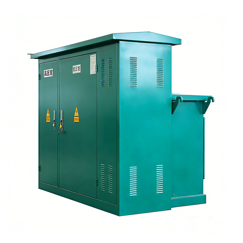
The American-type box substation is a compact prefabricated substation that integrates a transformer, high and low voltage switches, fuses, metering devices, and other components. The American-type bo...
See Details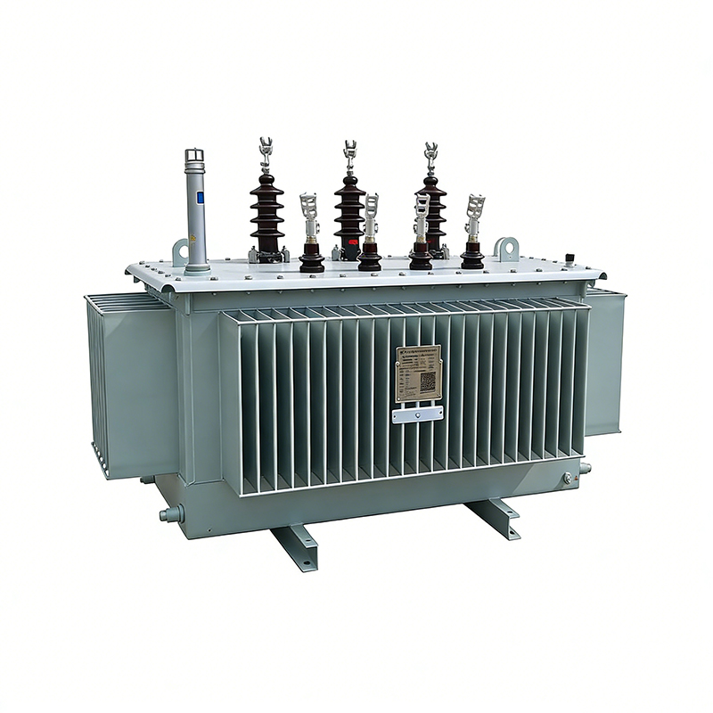
The amorphous alloy non-distribution transformer adopts an iron-based amorphous alloy wound core and a fully sealed oil-immersed corrugated oil tank structure. This transformer features extremely low ...
See Details
The GGD low-voltage switchgear is a low-voltage distribution device with a reasonable structural design, high breaking capacity, and reliable breaking performance. The switchgear is equipped with a co...
See Details
The KYN28 medium-mounted high voltage switchgear adopts a metal armored, removable enclosed structure. The switchgear has clear internal compartments and reliable safety performance. The switchgear is...
See DetailsHey! Interested in staying in the loop? Sign up for our updates. We won't spam you, pinky promise.

Taizhou Haitian Electric Manufacture Co., Ltd.
