Why Impedance Voltage Matters More Than kVA Rating When Specifying a Medium-Voltage Transformer
Buyers often compare medium-voltage transformer quotes purely on kVA rating and price, but the impedance voltage percentage is what actually determines how the unit behaves once it's energized. A lower impedance value (commonly 4% for smaller distribution units) allows tighter voltage regulation under load but permits higher fault current in the event of a short circuit, while a higher impedance value (5.5% to 6.5% on larger 35kV units) limits fault current at the cost of slightly larger voltage drop during sudden load changes. This trade-off directly affects downstream protection coordination, since breaker and fuse sizing has to account for the actual fault current the transformer will let through, not just its rated capacity.
For sites with sensitive equipment or long feeder runs, specifying impedance too low can create nuisance tripping during motor starts, while specifying it too high can cause voltage sag that affects variable-speed drives. With over 50 years of transformer manufacturing experience and annual production capacity exceeding 4 million kVA, Taizhou Haitian Electric Manufacture Co., Ltd. designs 35kV and below units with impedance values matched to the customer's fault-current study rather than defaulting to a standard percentage, which avoids costly rework during commissioning.
Harmonic Distortion and K-Factor Ratings in Low-Voltage Transformer Design
A standard low-voltage transformer is designed assuming a linear, sinusoidal load. Once a facility introduces variable-frequency drives, LED lighting drivers, or large UPS systems, the harmonic content in the current waveform generates additional eddy-current losses in the windings that a standard design doesn't account for. This is measured using a K-factor rating: a K-1 transformer assumes no harmonic loading, while K-13 and K-20 ratings indicate the unit has been designed with heavier gauge conductors and modified winding geometry to dissipate the extra heat generated by harmonic currents without exceeding insulation temperature limits.
Ignoring K-factor requirements is one of the most common causes of premature low-voltage transformer failure in facilities with modern electronic loads, since the extra heating is invisible on a standard load meter that only reads RMS current. Taizhou Haitian Electric Manufacture Co., Ltd. addresses this at the design stage by reviewing the customer's load composition before finalizing winding specifications, and its power products carry PCCC energy-saving certification (Level 2+), confirming that loss performance meets national efficiency benchmarks even under mixed load conditions.
Signs a Facility Needs a Higher K-Factor Rating
- Transformer runs noticeably hotter than nameplate rise despite load being under 80% of capacity
- Neutral conductor current exceeds phase current on a three-phase, four-wire system
- Facility has significant VFD, server, or LED lighting load added after initial transformer sizing
Insulation Coordination Between Medium-Voltage and Low-Voltage Windings
Operating with over 100 sets of advanced production and testing equipment across a 62,000㎡ facility, Taizhou Haitian Electric Manufacture Co., Ltd. tests insulation coordination as a standard part of production, since this is one of the most overlooked aspects of transformer specification. Insulation coordination refers to matching the basic impulse level (BIL), clearance, and creepage distance between the medium-voltage and low-voltage sides so that a lightning surge or switching transient entering from the primary doesn't puncture the secondary insulation before protective devices can react.
The two voltage classes require very different insulation margins, which is why a medium-voltage transformer and a low-voltage transformer are never interchangeable in terms of dielectric design, even at similar kVA ratings.
| Parameter |
Medium-Voltage Transformer (up to 35kV) |
Low-Voltage Transformer |
| Typical BIL rating |
150–200 kV |
10–20 kV |
| Minimum clearance distance |
270–320 mm |
Under 25 mm |
| Typical impedance range |
4.5%–6.5% |
2%–4% |
Loss Classification and Energy Efficiency Grading Explained
Every transformer, whether it's a medium-voltage transformer feeding a substation or a low-voltage transformer serving final distribution, carries two distinct loss categories: no-load loss (core loss, present continuously once energized) and load loss (winding loss, which scales with current squared). National efficiency grading systems classify units by both figures together, since a transformer with low no-load loss but high load loss may actually perform worse over its lifetime than one with a more balanced loss profile, depending on how heavily it's loaded on average.
For facilities running near-continuous load, prioritizing low no-load loss units delivers the biggest lifetime savings, while intermittently loaded applications benefit more from minimizing load loss. Getting this wrong is a common reason energy audits flag transformers that technically meet minimum efficiency standards but still underperform in practice.
Certifications Worth Verifying Before Purchase
- National test reports confirming independent intellectual property and compliance with GB standards
- Energy management system certification such as ISO50001, confirming ongoing efficiency monitoring at the manufacturing stage
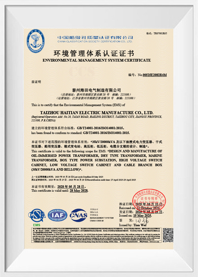
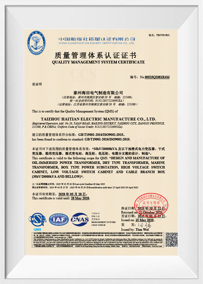
- Environmental and quality management certifications such as ISO9001 and ISO14001
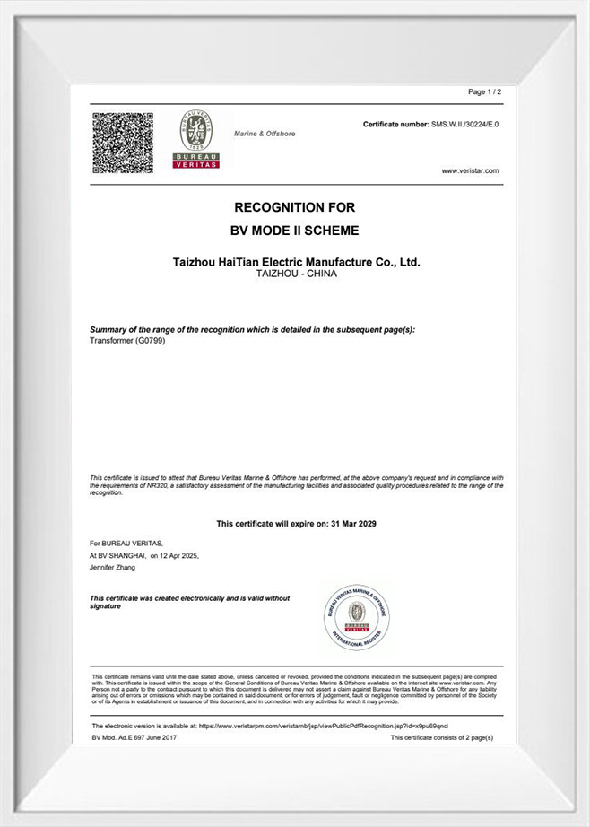
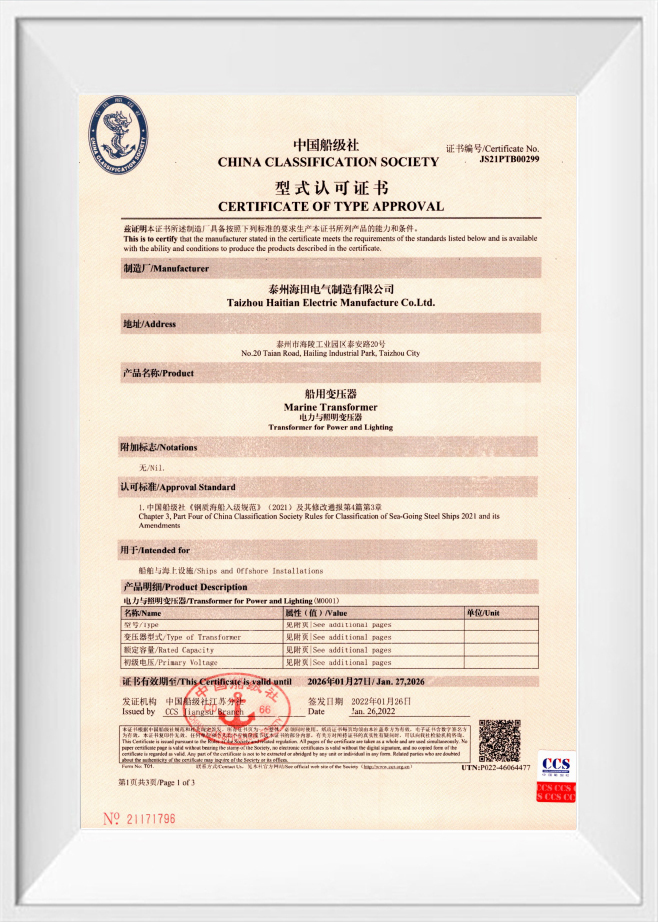
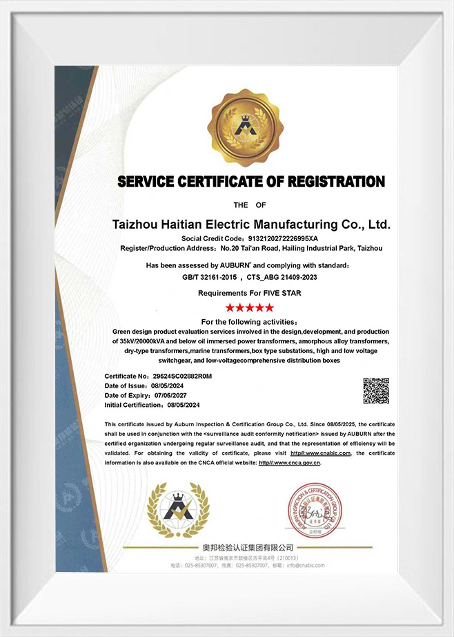
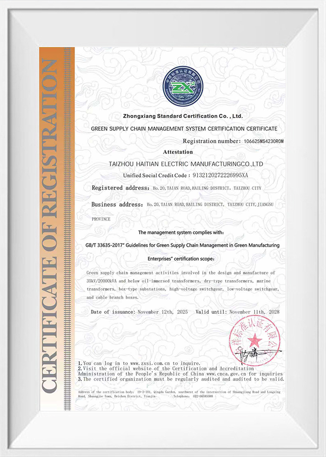
Taizhou Haitian Electric Manufacture Co., Ltd. holds ISO9001, ISO14001, GB/T28001, and ISO50001-2018 certifications, along with green supply chain, carbon footprint evaluation, and greenhouse gas verification credentials, and has been recognized under the Jiangsu Green Factory Certificate — documentation that gives procurement teams a verifiable basis for comparing efficiency claims across suppliers rather than relying on nameplate figures alone.

 English
 русский
 Français
 Español
 عربى
عربى